
The CPUID Explorer:
Part 1: The program
|
|
Home |
 |
Back To Tips Page |
| To Part 2 |
 |
The CPUID Explorer:
|
|
WARNING! This is a project that is still under construction. Both the code and the documentation are still being worked on. Feedback would be appreciated.
REQUEST: I would appreciate if you could run this on your machine and send me the resulting .cpuid file, so I can build a database of all kinds of machines for visibility. You can read the .cpuid file and assure yourself that no proprietary or confidential information is being transmitted.
 The CPUID instruction is a fairly complex instruction. Its purpose is
to return information about the processor properties. These can be useful for
many purposes, including optimizing certain regular computations to take
advantage of the properties of the cache. However, the discussion of how this is
done is outside the scope of this article.
The CPUID Explorer is designed to show you, in a graphical format, the informtion returned by the CPUID instruction, and when appropriate, it will decode the information and provide textual representations as well.
Like most of my projects, this project has two aspects: the actual CPUID instruction display, and a set of Windows programming techniques. The programming techniques are covered in a companion essay. (Note: as of 10-Mar-07, this essay has not been written)
Other things to note about the CPUID instruction is that it is a serializing instruction. That is, when it is executed, it stops all concurrent, speculative, and pipelined executions. All instructions which have been issued up to the point of the CPUID instruction must complete before the processor is permitted to proceed, and no instructions will be dispatched until the CPUID instruction has completed. The CPUID instruction is the only non-privileged serializing instruction available to user-level programmers (all other serializing instructions can only be executed in Ring 0, that is, in the kernel).
The most common usage of this is when the Time Stamp Counter (TSC) is read directly by an application, using the RDTSC instruction. The RDTSC instruction is not a serializing instruciton, and consequently it is possible that some of the instructions which follow it have already been issued before the TSC is read, or existing instructions have not yet completed, thus resulting in an inaccurate measurement of the time interval. The proper way to use RDTSC is to precede it by a CPUID instruction so that no instructions are issued early and all instructions have completed.
The CPUID instruction is a non-privileged instruction, and can be called in user space. It nominally takes in the EAX register a code that tells what information should be returned, and returns values in the EAX, EBX, ECX and EDX registers.
There are two special exceptions to how CPUID is used. When the input parameter is 2, it returns information including how many times a CPUID with value 2 in EAX needs to be called to get all the relevant information. The other case is when the input parameter is 4, the value in the ECX register tells which cache level of information to deliver.
The CPUID Explorer is currently targeted only to 32-bit x86 systems, because it uses inline assembly code to issue the CPUID instruction. The 64-bit compiler does not support inline assembly code insertions. The 64-bit compiler has an intrinsic __cpuid instruction, but unfortunately it is incorrectly implemented in the Microsoft compiler. It fails to load the ECX register (apparently the compiler writer never actually read the documentation on the CPUID instruction, or read only the first paragraph, and decided this was sufficient knowledge to do the implementation...)
This project has three components
This came about for a variety of reasons. One was an interest in modifying an algorithm to take advantage of cache strategies on a target architecture. Probably the most compelling reason for doing this was I needed something to occupy my time during a long overseas flight.
The CPUID Explorer is a program which reads all of the relevant parameters it can using the CPUID instruction and displays them in a human-readable form. It allows you to readily see all the parameters the architecture is capable of telling you. Using this information, you can consider ways to utilize it. However, be aware that some of this is highly non-portable, and can be quite different on different architectures. The AMD architectures, for example, are quite different from the Intel architectures, and the CPUID instruction returns information in a different format for these architectures. So the problem is not necessarily straightforward. But this can provide a start.
Each parameter to the CPUID instruction (nominally EAX, but sometimes EAX, ECX) will display in a separate page. In some cases, the register displays are so detailed that only one register will sensibly fit on a single page.
The pages displayed by the CPUID instruction are shown below. Note, however, that on any given machine, the actual number of pages displayed may be different; on some machines the CPUID instruction does not support all the features shown in the snapshots here, and for those features not supported, the page will not be displayed.
To make it possible to create and debug this application, since I was doing the work largely on my laptop which has a limited CPUID repertoire, I have a special feature when it is compiled in Debug mode: all pages are displayed, but those which are unsupported are shown with all controls disabled. The information which displyed in these disabled pages is not meaningful, and this is solely done as an aid to the developer.
The following CPUID calls, which are all that are defined in the Intel and AMD documentation, are currently supported, when available.
- basic CPU informationThe program attempts to construct a block diagram of the machine architecture. An example is shown below.
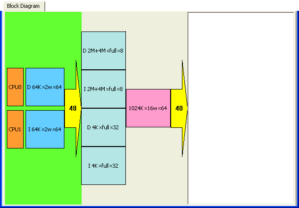
The left shows the number of logical CPU cores on the chip on which the program is running. The next group over displays the L1 cache. Then the number of bits of virtual address supported are shown. This is all displayed as part of the CPU box. Then the next grouping is the Translation Lookaside Buffers (TLBs) that handle the page translations, followed by the L2 cache parameters. If there is an L3 cache, it would appear next, but this architecture has no L3 cache, so the next box is the arrow showing the number of physical address lines available on the chip. The large white area is the physical memory, and there is not currently any support to fill this in; this will be in a future release of the program. More extensive flyover (tooltip) help will also be added.
In addition to reading the CPUID information from the current processor, it is possible to write a data file which contains information about the current processor. This configuration file can be then read in to the program running on any other machine. This allows for remote support where CPU information may be relevant, particularly for a program that is trying to take advantage of the platform-specific information.
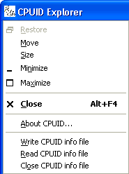 These operations are
available via the system menu.
Write CPUID info file is only available when there is no current CPUID information file. The file is in XML format and has the extension .cpuid.
Read CPUID info file will read a previously-saved CPUID information file, which is a .cpuid file. It will read in the CPUID file and reconfigure the program to act as if it were running on that system. Only the tabs that would be visible on that machine are visible. Note that the ability to select which CPU the CPUID Explorer is running on is disabled.
Close CPUID info file closes the previously-open CPUID information file, and reverts to running on the current machine. It reconfigures the program to display only the relevant information for the current machine.
There is a module CPUIDx86.cpp, and its header file, CPUIDx86.h, which supports the 32-bit CPUID interface.
BOOL CDECL GetCPUID(UINT type, CPUregs * regs);
The type is the input parameter to the CPUID instruction. It is the value placed in the EAX register. The only values which are guaranteed to be supported on all architectures are 0 and 0x80000000. Each of these will return a value in EAX which is the largest permitted value for subsequent CPUID instructions.
Notationally, I will represent the call of the CPUID instruction with value n in the EAX register as CPUID(n).
The regs parameter is a pointer to the structure below.
typedef struct {
    ULONG EAX;
    ULONG EBX;
    ULONG ECX;
    ULONG EDX;
} CPUregs;
The structure is nominally output-only, but the value of ECX in the structure will be loaded into the ECX register before doing the CPUID instruction. In all cases except code CPUID(4) this value is ignored by the instruction and overwritten, but for CPUID(4) it selects which cache parameter information is provided. The permitted values for CPUID(4) are 1, 2 and 3 for now; values 4..32 are reserved for future use. Value 0 is not a permitted value. Notationally, I will represent the call of CPUID(4) with value n as CPUID(4, n).
The call is specified to return FALSE if the CPUID instruction is unsupported. However, since there are no machines today that can run Windows that do not support the CPUID instruction, I have not implemented code to perform this test.
A typical set of calls might be
CPUregs regs; GetCPUID(0, ®s); MaximumBasicCPUIDcode = regs.EAX;
GetCPUID(0x80000000, ®s); MaximumExtendedCPUIDcode = regs.EAX;
The values returned by the CPUID instruction are of these forms
The raw register values are always displayed in the window above the tabbed dialog. The interpreted register values are displayed in the appropriate tabbed dialog. Switching tabs causes the appropriate CPUID instruction to be executed at that point, and the values will change to represent this new execution.
When a set of bit fields is used, the display looks similar to the one shown below. Each field is in a color, and its descriptive text is in the same color. The colors were chosen so that black text is readable against the color (ideally). This set of colors is fixed, but there is a table in the source code that can be changed to change the set of colors. The colors are used in a round-robin order from the known set of colors.
The values are displayed in decimal, unless suffixed by B indicating binary or H indicating hexadecimal.
When a numeric display is required, the value is displayed in decimal or hexadecimal.
When a textual display is required, the value is displayed as a quoted string. A character whose value is 0x00 is displayed as \0.
When an entire register value is reserved, the contents are generally not displayed. When a bit field is reserved, its value is displayed, and the highlighting color for reserved fields always uses the same color.
In some cases, the value displayed is not overly useful. Instead, a meaningful value (such as a readable string) must be computed from the information displayed. Sometimes this is done by looking the value up in a table (the lookup strings are documented, and you may copy them from this project to one of your own if you need the displayed value), and sometimes it is done by a computation based on the value (concatenating bit fields, adding bit fields, or adding 1 to a bit field value are typical examples). These computed values will be displayed in addition to the information presented.
If the display is different on an Intel and AMD platform, the platform type will appear in the lower left corner of the window.
Whenever a value in a register is a bit field, there is always an accompanying struct that defines the fields. The structs have canonical names based on which CPUID(n) code and register is used. Nominally the names are of the form ErXnd, where r is the register name, {A, B, C, D}, n is the decimal value of the low-order byte of EAX used for the CPUID instruction, and d indicates if it is a basic or extended call {b, x}.
The following structures are defined
These will be examined in detail in the accompanying essay on the CPUID instruction.
The general structure of these structs is
typedef union {
     struct {        // low order
             UINT fieldname:width;   // n..m
                 ... repeat above line for each field
                 ... the sum of all width values must be 32
            } platform;  // high order
     UINT w;
} ErXnd;
To access the values, you assign the appropriate register contents from the selected register to the
w member and read the values out from the structure member. The
platform indicates the platform involved, and is one ofNote that in some cases, there are the same fields assigned for both Intel and AMD.
In this example, a test is made to see if the CMPXCHG16B instruction is supported on this architecture.
CPUregs regs;
GetCPUID(1, ®s);

ECX1b ECX;
ECX.w = regs.ECX;
if(!ECX.Intel.CMPXCHG16B)
   { /* CMPXCHG16B not supported */
    ...
   } /* CMPXCHG16B not supported */
These structures cann be found in the file CPUIDRegs.h.
At the top of the dialog is the common register information. The unlabeled box in the top left corner is the value of EAX on input to the CPUID instruction. The remaining four boxes are labeled with the register name of the register, and contain the output from the CPUID instruction. These are the "raw" register values. They are nearly unintelligible when bit fields are involved.

Note that in a multiprocessor system, you might want some assurance that these values are from a specific processor. The CPU selection is enabled for multiprocessors. This snapshot was taken from a uniprocessor. (It is actually unlikely you would get different values from a different CPU in the mix, because the requirements of Windows for Symmetric Multiprocessing, down to the step level of the silicon. On the other hand, if you are having trouble, this is a simple way to determine if you have violated this restriction with a heterogeneous mix of processors).
CPUID(0)
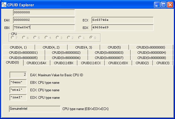
This illustrates several of the display styles. The contents of EAX are a simple integer, the maximum value of CPUID that is supported for this processor (this snapshot was deliberately done from the Debug version so all tabs are installed and visible). The values in EBX, ECX, and EDX are character strings, so are shown quoted. The resultant CPU type name is a computed value and is the concatenation of the three register values.
CPUID(1):EAX
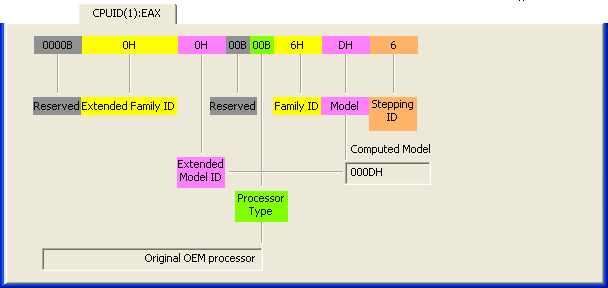
This page illustrates a typical example of a display of fields. The fields and their labels are highlighted in matching colors, and the Reserved fields are all the same medium-dark gray color.
Note that the reserved fields are displayed in binary, the other fields, except the stepping ID, are displayed in hexadecimal, and the stepping ID is displayed in decimal. There is no ambiguity that 0000B might be the hexadecimal equivalent of 11 because in that case it would have been displayed as 0000BH. The processor type is also displayed in binary because that is how the documentation explains the values.
There are two computed fields shown here.
In this case, a documented algorithm for computing the model ID is used. The model ID is documented according to the following pseudo-code
if(familyid == 0x6 || familyid == 0xF)
   computed model = model + (extended model << 4)
else
   computed model = model;
As it turns out, the extended model number here is 0H so the computed model appears to be the same as the basic model, but the algorithm has been applied. This particular item will not be displayed if the family ID is other than 0x6 or 0xF.
The processor type is decoded according to a lookup table based on the documented processor types.
ToolTip Help
When a bit field is displayed, hovering the mouse over it will pop up a tool tip giving the bit field within the register, as shown below.
![]()
CPUID(1):ECX
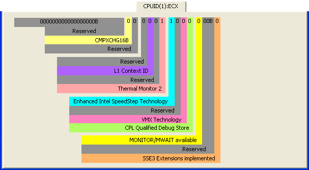
This is another example of showing bit fields. In this case, the bit field descriptions are visually extended to the layout of the register. When feasible, the bits are grouped by nybbles.
![]()
The views expressed in these essays are those of the author, and in no way represent, nor are they endorsed by, Microsoft.